What is geotechnical instrumentation?
Geotechnical instrumentation is the set of sensors and survey targets we place in soil, rock, and structures to measure how they actually behave during and after construction. The main quantities we track are ground movement, pore water pressure, stress and load, and strain.
The key idea: design is based on assumptions about the ground. Instrumentation tells us whether those assumptions hold in the field.
Why
Safety. Monitoring picks up early signs of instability so the team can act before a failure, collapse, or landslide develops.
Optimization. Field data validates design assumptions. If the ground performs better than predicted, support or construction methods can sometimes be refined. If it performs worse, the design can be adjusted in time.
Compliance. Owners, agencies, and third parties such as railroads, utility owners, and adjacent property owners often require monitoring as a condition of approval.
Most projects define two response levels for each instrument. A threshold (review) value triggers closer review and more frequent readings. A limiting (alert) value triggers a stop work order or predefined mitigation. These are usually documented in a Trigger Action Response Plan.
Instrument categories
| Category | What it measures | Typical instruments |
|---|---|---|
| Displacement | Ground and structure movement | Surface points, prisms, inclinometers, extensometers, settlement plates, tiltmeters |
| Pressure and load | Water pressure, earth pressure, loads, strain | Piezometers, pressure cells, load cells, strain gauges |
| Environmental | External influences | Seismographs for vibration, thermistors for temperature |
Ground movement monitoring
Surface/Structural movement points
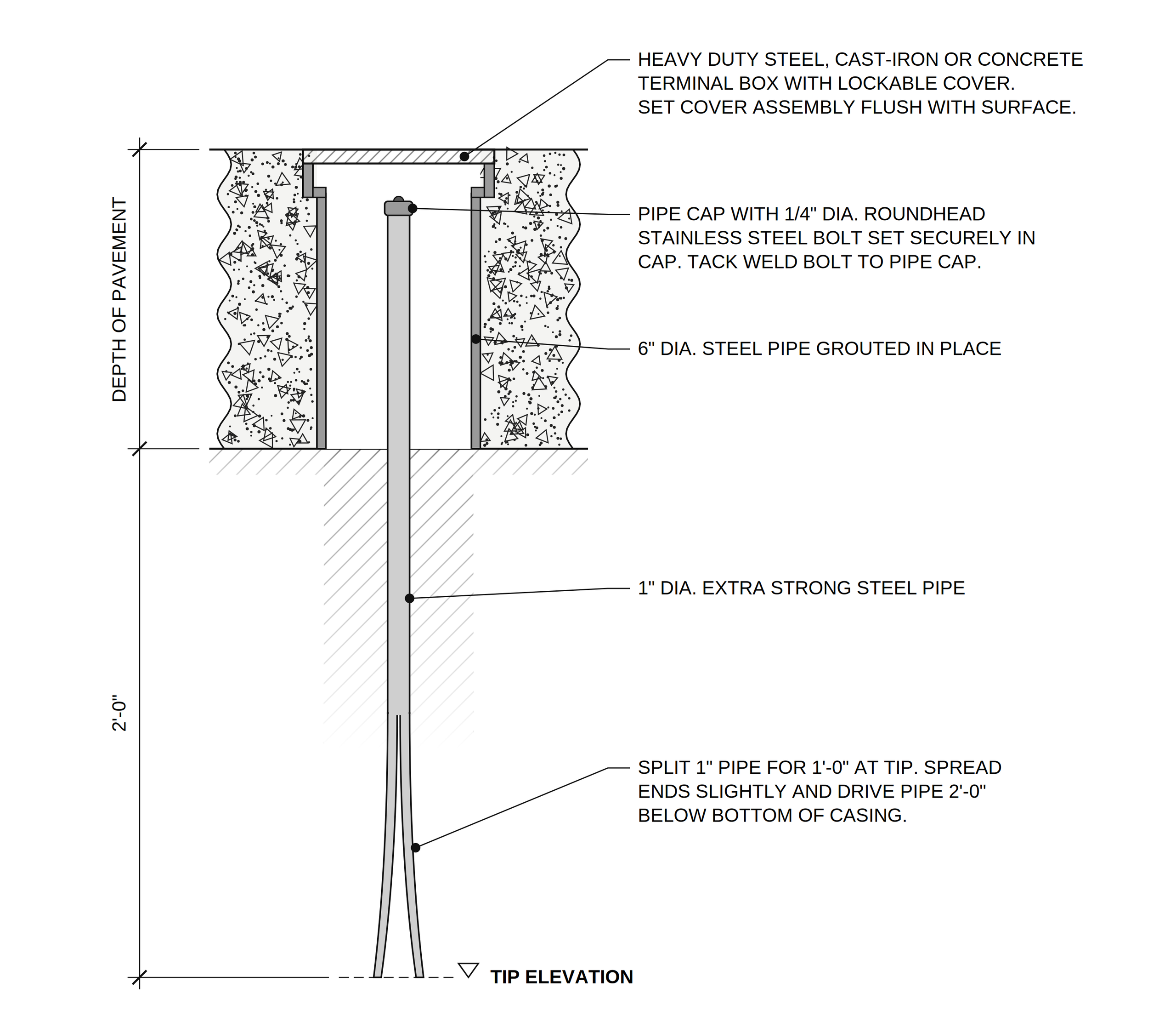
Survey points set in pavement, soil, or structures and read with precise leveling or a total station. Under pavement, a deep point is used: a small-diameter pipe driven below the pavement section inside a larger grouted casing. The annulus between the two pipes is kept free of grout so the point moves with the soil, not the pavement. Building points typically use a stainless steel bolt in an expansion anchor with an identification tag.
Utility monitoring points
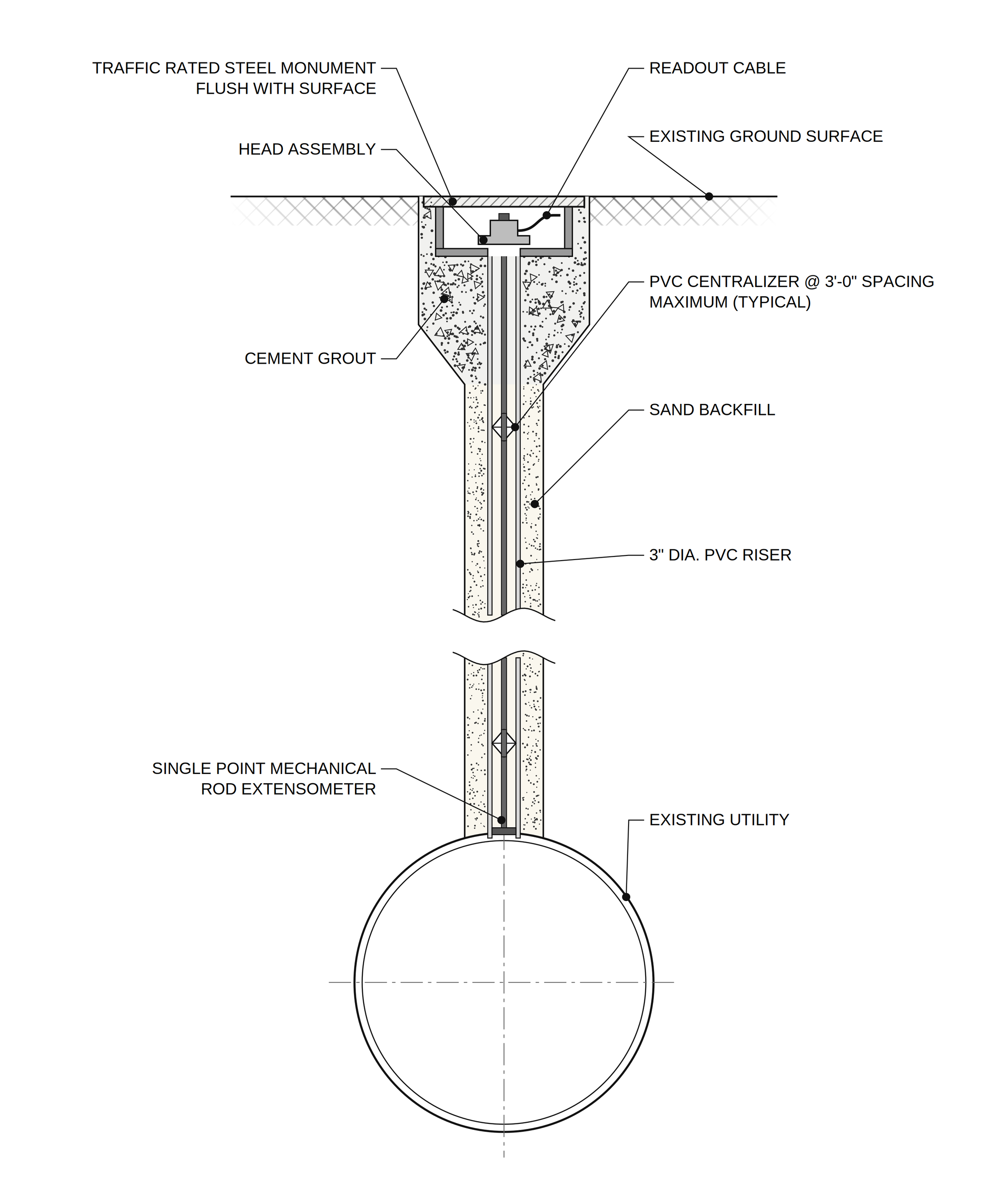
Used where excavation, dewatering, tunneling, or trenching could move a buried utility. A single point rod extensometer is installed in a riser down to the top of the utility and read at a traffic rated monument at the surface. This measures the utility itself rather than the ground above it.
Deformation monitoring prisms
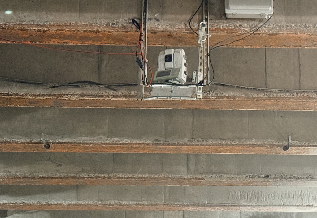
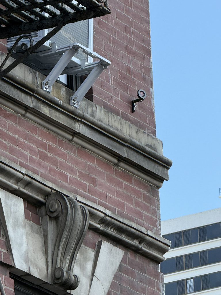
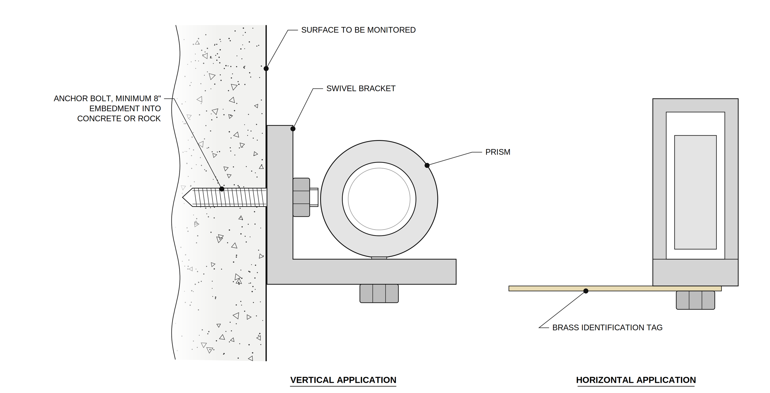
Reflective targets mounted on structures, walls, or tunnel linings with a swivel bracket and an anchor bolt with at least 8 in. of embedment into concrete or rock. They are read by a total station, often a robotic unit running on an automatic schedule. Reference prisms must sit outside the zone of influence of the work so they provide a stable baseline.
Inclinometers
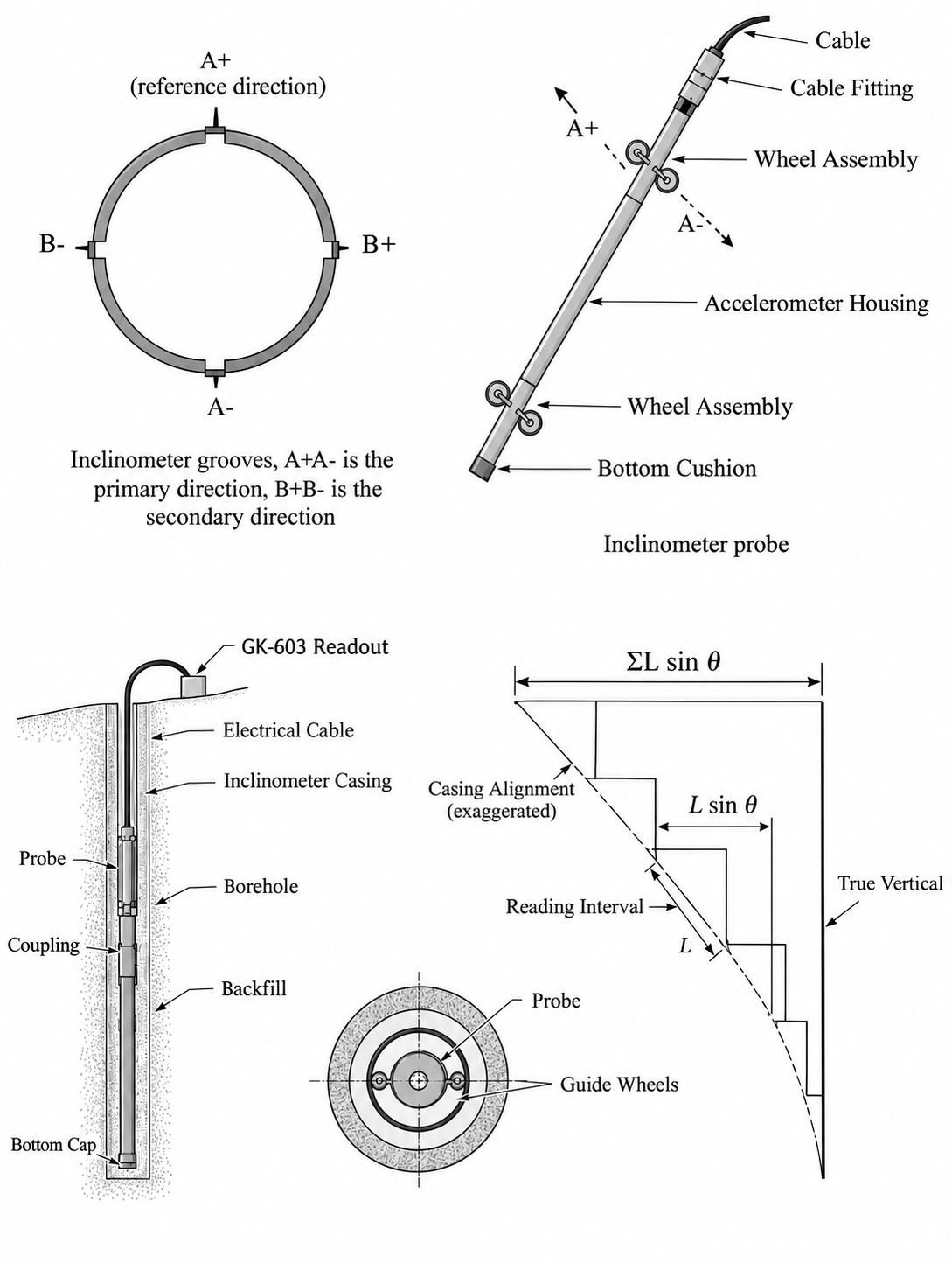
Inclinometers measure lateral movement with depth in slopes, retaining walls, and excavations.
- A grooved guide casing is grouted into a borehole and founded in stable ground below the expected movement.
- A probe with a gravity sensing transducer is lowered along the grooves and read at fixed intervals, commonly 2 ft or 0.5 m.
- At each interval the probe measures tilt
- Summing from the fixed bottom upward gives the displacement profile.
- Comparing each survey to the baseline profile shows where and how much the ground is moving.
Settlement plates
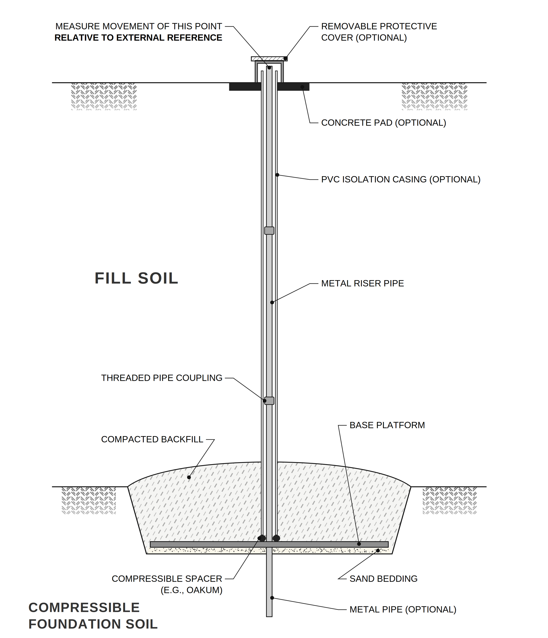
A base plate set on the compressible foundation soil with a riser pipe extended up through the fill. The top of the riser is surveyed against an external benchmark. An optional PVC isolation casing keeps the fill from dragging on the riser. Settlement plates are common on embankments, foundations, and landfills to track consolidation.
Extensometers
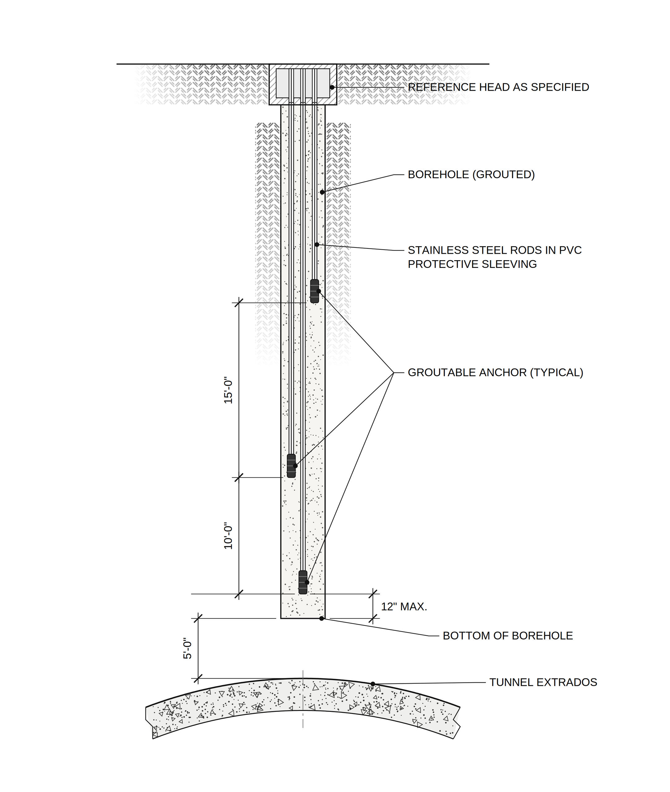
Extensometers measure the change in distance between anchors at different depths and a reference head at the surface. A multipoint rod extensometer above a tunnel might have anchors at 5 ft, 10 ft, and 15 ft above the extrados. Comparing anchors shows where in the soil column the movement is happening, which surface points alone cannot tell you.
Tiltmeters
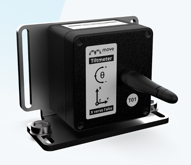
Mounted on structures with a bracket to measure rotation, usually on two axes. Small rotations can reveal differential settlement or foundation distress well before cracking appears.
Pore water pressure
Standpipe piezometers
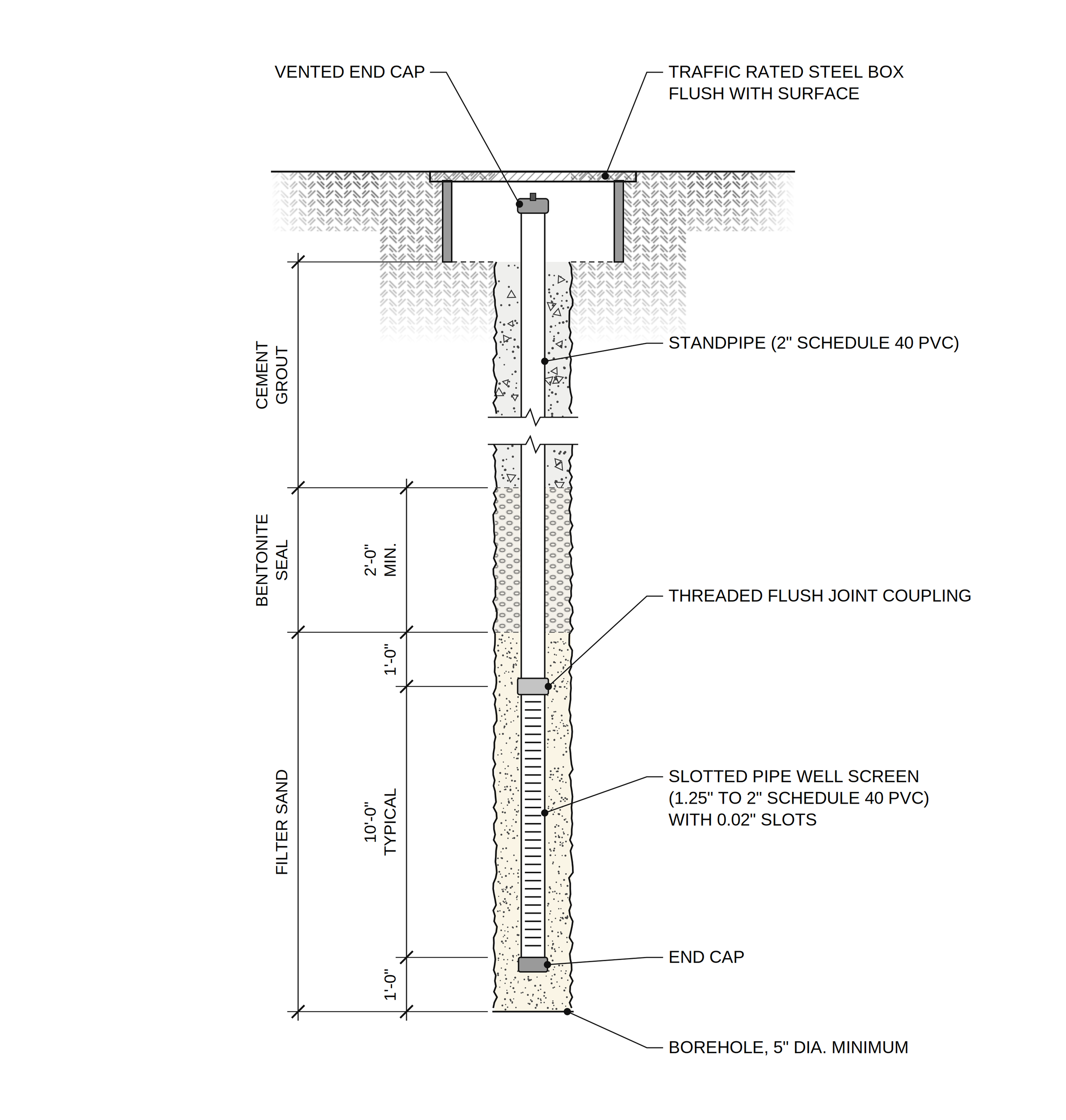
A slotted well screen surrounded by filter sand, sealed above with at least 2 ft of bentonite and then cement grout to the surface. The water level is measured manually with a dip meter. They are simple, inexpensive, and easy to verify, but readings are manual and response is slow in low permeability soils such as clay.
Vibrating wire piezometers
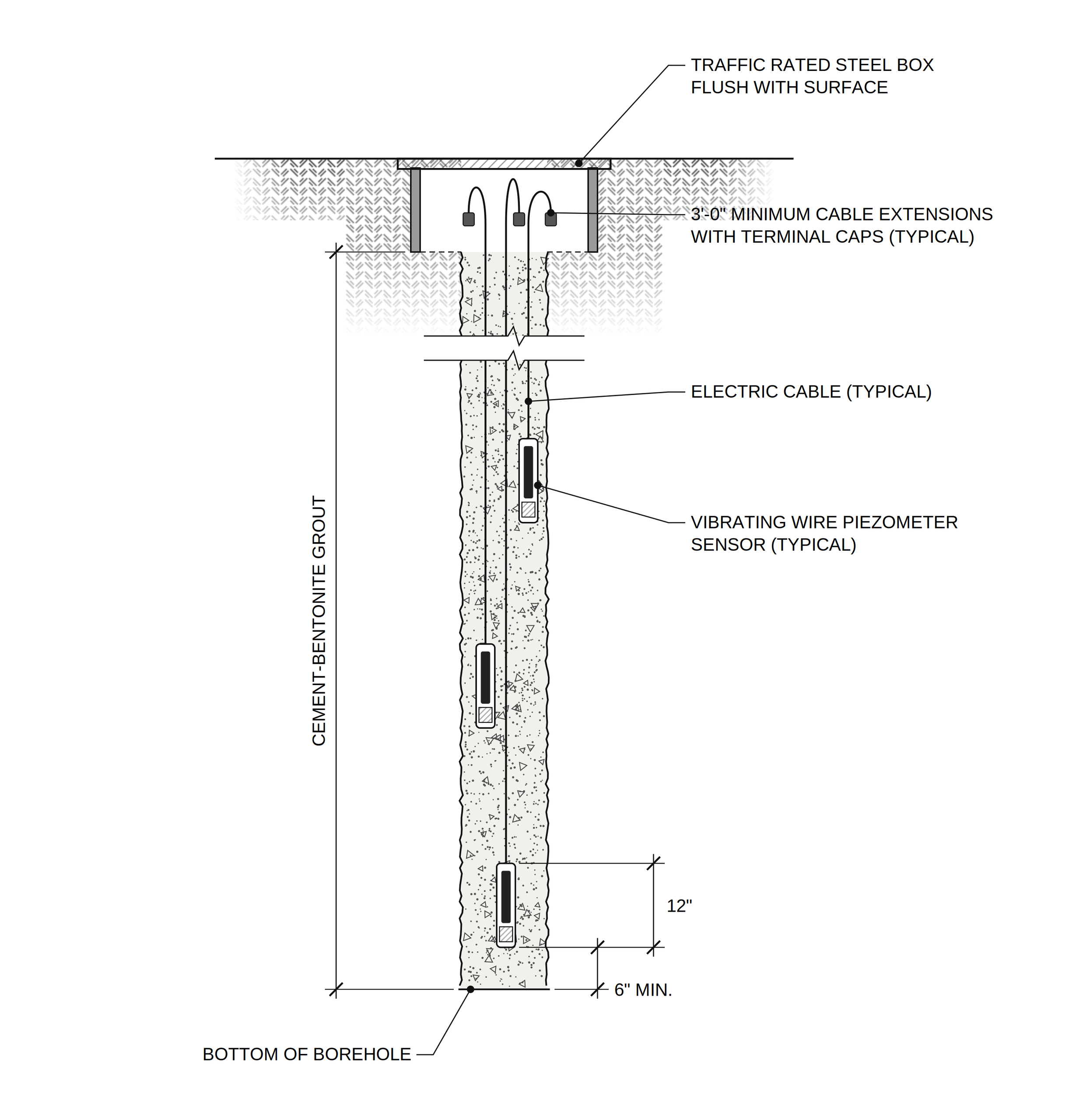
Water pressure deflects a diaphragm, which changes the tension in a steel wire and therefore its resonant frequency. The readout converts frequency to pressure using the manufacturer calibration factor with a temperature correction. They respond quickly, work well with data loggers, and are stable over the long term. Several sensors can be placed at different depths in one borehole backfilled with cement bentonite grout.
Load and stress monitoring
Load cells
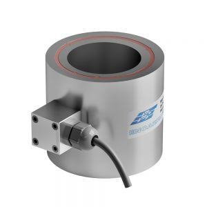
Load cells are hollow cylinders placed between the bearing plate and anchor nut of a rock bolt, tieback, or strut. They confirm that loads stay within design limits and show load loss over time.
Pressure cells
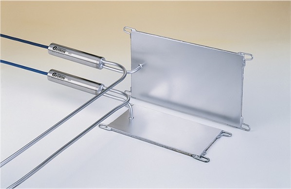
Pressure cells are two thin plates welded together with fluid between them. Earth pressure on the plates is read by a transducer. In shotcrete or concrete linings, a pinch tube is used after curing to restore contact between the cell and the concrete.
Strain gauges
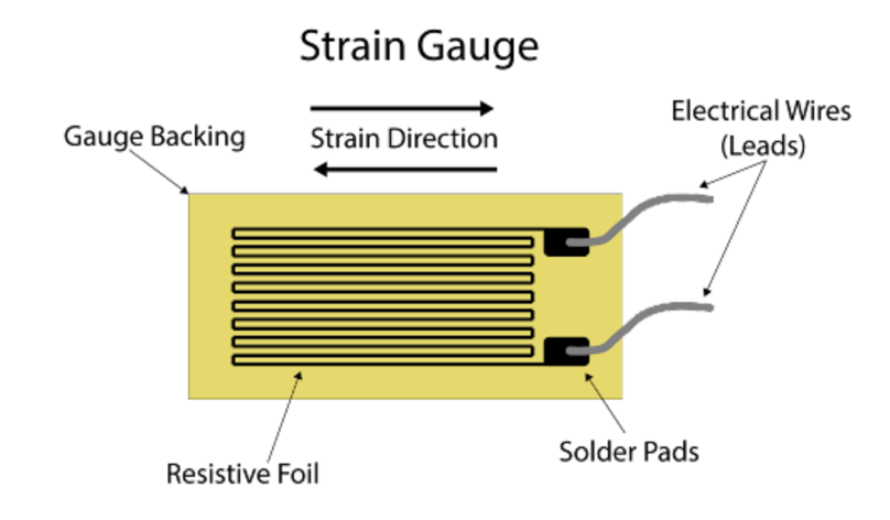
Strain gauges measure strain in beams, columns, struts, and tunnel linings. Foil resistance gauges work well on steel. For concrete and long term monitoring, vibrating wire strain gauges are more common. Stress is estimated from strain using the material modulus.
Planning, installation, and data
Selection. Start with the question you need answered, then pick the instrument. Consider the expected magnitude of movement, required accuracy, site conditions, access, and how long monitoring will last.
Installation. Follow manufacturer procedures, calibrate before installation, record as built locations and depths, and take stable baseline readings before construction starts. A poor baseline weakens every reading that follows.
Data collection. Manual readings suit small projects and low frequency needs. Automated data loggers and wireless systems suit large or high risk projects where near real time alerts matter.
Analysis. Plot readings against time and against construction activity such as excavation depth, TBM position, or dewatering. Look at trends and rates, not just the latest value.
Presentation. Time history plots, inclinometer profiles, settlement contour maps, and 3D models.
Common problems. Sensor drift, calibration errors, damaged instruments, and data transmission failures. Regular maintenance, redundant instruments, and QC review of every data set address most of these.
Software. GeoStudio (SLOPE/W) for slope stability, PLAXIS for soil structure interaction modeling, and logger or vendor software for real time data acquisition.
Key takeaways
- Every instrument should answer a specific question about ground or structure behavior.
- Good baselines and careful installation matter as much as the sensor itself.
- Threshold and limiting values turn data into decisions.
- Interpret trends and rates alongside construction activity, not isolated numbers.